硬质合金数控雕刻钻头 提供现代铣床主轴速度下精细加工所需的硬度、耐磨性和切削刃稳定性。与许多高速钢刀具相比,当几何形状和切削参数与材料正确匹配时,整体硬质合金刀具可以更长时间地保持锋利轮廓。
硬质合金数控雕刻钻头的优点
主要优点是可预测的切削性能。刚性硬质合金主体可抵抗偏转,而精密磨削的边缘可再现精细的文字、徽标、凹槽和三维细节。这种组合支持标牌制作、木工、塑料加工和工艺品生产中清洁的表面、精确的尺寸以及更长的工具更换间隔。
- 高硬度: 在重复雕刻操作过程中保持切削刃。
- 耐磨性: 支持磨料木材、中密度纤维板、塑料和复合材料的更长使用寿命。
- 尺寸稳定性: 减少精细刻字和详细图案时的偏转。
- 清洁切割: 锋利、抛光的边缘有助于减少毛刺和后处理。
- 高速能力: 适用于在推荐范围内进行高效 CNC 铣床操作。
硬度和边缘保持力
硬质合金在切削温度下保留有用的硬度,这可能会软化其他刀具材料。但这并不意味着它坚不可摧:硬质合金相对较脆,需要低跳动、刚性工件夹具和受控进给。当设置稳定时,边缘可以在更长的生产运行中保持精确,并保持一致的雕刻深度。
表面光洁度和切屑控制
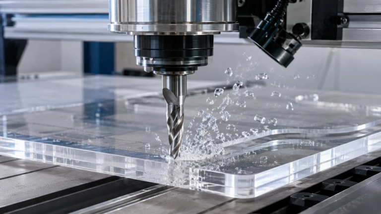
容屑槽的几何形状决定切屑离开切削区域的方式。单槽设计通常为丙烯酸和塑料提供充足的切屑空间,而双槽和特殊的雕刻几何形状则满足其他材料和光洁度要求。抛光的凹槽可以减少切屑粘附,并且合适的涂层可以帮助控制选定应用中的摩擦或树脂堆积。
材料和 CNC 雕刻应用
硬质合金 CNC 雕刻钻头适用于木材、胶合板、MDF、丙烯酸、PVC、工程塑料、层压板和选定的有色金属材料(当工具专为该工作而设计时)。典型工作包括标牌、铭牌、标志、家具装饰、浮雕、模型制作、珠宝图案、工艺部件和精密凹槽。
物质行为很重要。木纹会撕裂,中密度纤维板会磨损,丙烯酸会熔化,脆性塑料会碎裂。选择适合工件的切削直径、刀尖角度、凹槽形状、涂层和边缘抛光,而不是期望一把刀具在任何地方都表现得同样出色。
如何选择正确的雕刻刀头
从设计中最小的特征和所需的雕刻深度开始。较窄的尖端可以产生精细的细节,但强度较低,而较大的直径则更坚硬,可以更快地去除材料。确认柄部直径适合夹头,并保持刀具突出尽可能短,以减少振动。
- 将刀具材料和几何形状与工件相匹配。
- 确认刀尖直径、切削角度、槽长、刀柄和总长度。
- 精细雕刻前,使用干净的夹头并检查主轴跳动。
- 从保守的速度、进给和切削深度设置开始。
- 检查切屑和表面质量,然后一次调整一个参数。
操作和维护技巧
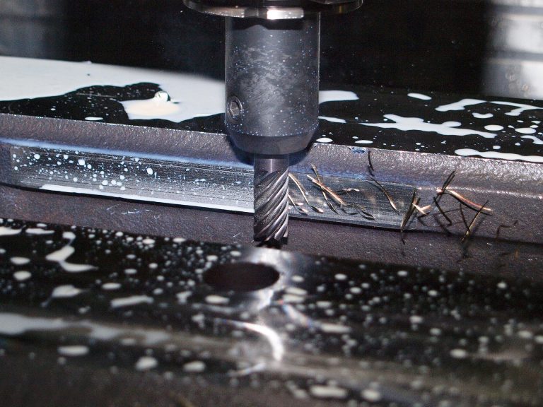
开始前固定工件、验证刀具路径并确认足够的间隙。切屑负载必须足够高,以实现高效切削,但切屑负载不能太大,以免小雕刻边缘偏斜或断裂。有效的集尘或气流有助于防止切屑被重新切削并减少刀具周围的热量。
使用后,清除树脂和碎屑,不要撞击边缘。将每个钻头单独存放在干燥支架中。当雕刻宽度增加、细角变圆、出现毛刺或切割噪音变化时,更换或专业打磨磨损的刀具。继续使用钝的刀具可能会使工件过热并使主轴拉紧。
广东省广州市硬质合金雕刻钻头供应商
JEEFOO 为经销商、标牌制造商、木工工厂、CNC 车间和国际买家提供来自中国广东广州的硬质合金 CNC 雕刻头。客户可以在订购前确认材料、机器、尺寸和表面处理要求。探索 JEEFOO CNC cutting tool range 用于雕刻、铣削和铣削解决方案。
常见问题解答
为什么硬质合金比高速钢使用寿命更长?
硬质合金具有更高的硬度和耐磨性。使用寿命仍然取决于材料、几何形状、跳动、切屑负载、冷却和机器稳定性。
哪种钻头最适合亚克力雕刻?
通常首选具有抛光边缘和足够排屑槽空间的锋利刀具,因为它可以排出切屑并限制热量。根据亚克力等级、厚度和所需细节选择几何形状。
如何减少刀具破损?
最大限度地减少跳动,使用刚性工件夹具,缩短刀具突出部分,避免深度过大,并保持合适的切屑负载。一般流程背景可在此处找到 engraving overview.
Carbide CNC Engraving Bits: Practical Selection and Maintenance Notes
Carbide CNC engraving bits are made for users who need a stable cutting edge during repeated routing and engraving operations. Their high hardness helps the edge retain its shape under normal cutting temperatures, while the rigid tool body helps reduce deflection during fine lettering, logos, grooves, and three dimensional details. These advantages are most valuable when the machine, collet, fixture, feed rate, spindle speed, and material are matched as a complete machining system. A carbide bit is not a substitute for a rigid setup, but it can provide a dependable foundation for accurate work.
The first selection factor is the workpiece. Wood, plywood, MDF, acrylic, PVC, engineering plastics, laminates, and selected non ferrous metals each produce different chips and heat. A single flute geometry often provides generous chip space for acrylic and plastic, helping chips leave the cutting zone before they soften and stick. Woodworking applications may require a different flute count or cutting angle to control grain tear out. For aluminum, the operator should prioritize rigidity, sharp edges, controlled engagement, and effective chip removal. Always verify the recommended diameter and shank size before loading the tool.
Hardness and wear resistance are important, but edge life also depends on runout and vibration. A dirty collet, worn spindle, loose workholding, or excessive tool overhang can cause a carbide tool to chip even when the cutting parameters appear reasonable. Before a job, clean the collet and shank, inspect the cutting edge under good light, and confirm that the tool is seated straight. Clamp the shank securely without covering the flute. Keep the stick out as short as the design allows, especially for narrow engraving tools and deep details.
Surface finish is strongly affected by chip control. When chips remain in the groove, the tool may recut them, creating heat, burrs, discoloration, or a rough finish. Use air blast, extraction, or another suitable evacuation method for the material and machine. If acrylic starts to melt, reduce heat generation and check whether the tool is rubbing. A modest increase in feed, a shallower pass, better airflow, or a sharper tool can solve the problem. If wood fibers tear, review grain direction, tool sharpness, entry strategy, and the final finishing pass.
A reliable setup sequence begins with a small test cut. Secure the workpiece, set the origin, check the safe height, and run an air cut when the design or material is unfamiliar. Start with a shallow depth and moderate stepover, then change only one variable at a time. Measure line width, depth, burr formation, and surface finish after the test. Recording successful parameters by material creates a repeatable process and helps operators compare tools fairly. Several light passes are generally safer than one deep pass when the goal is clean detail and long tool life.
Maintenance should be simple and consistent. Remove resin, dust, and chips after use with an appropriate brush or controlled air stream. Do not strike the cutting edge against a hard surface, and store each bit in a protective case so the carbide tip cannot contact other tools. Replace a tool when it produces persistent chatter, an uneven line, increased cutting force, repeated burrs, or visible edge damage. JEEFOO supports CNC tooling users with carbide engraving bits and selection information for sign making, woodworking, acrylic routing, plastic machining, and detailed production work.
Frequently asked questions include whether carbide bits can be used for plastics, why a rigid collet matters, how to reduce burrs, and when a bit should be replaced. The practical answer is to match the flute geometry to the material, control heat, evacuate chips, limit overhang, and keep the workpiece firmly supported. These habits allow the hardness, wear resistance, dimensional stability, and clean cutting performance of carbide CNC engraving bits to deliver consistent results across small prototypes and longer production runs.
Carbide CNC Engraving Bits: Practical Selection and Maintenance Notes
Carbide CNC engraving bits are made for users who need a stable cutting edge during repeated routing and engraving operations. Their high hardness helps the edge retain its shape under normal cutting temperatures, while the rigid tool body helps reduce deflection during fine lettering, logos, grooves, and three dimensional details. These advantages are most valuable when the machine, collet, fixture, feed rate, spindle speed, and material are matched as a complete machining system. A carbide bit is not a substitute for a rigid setup, but it can provide a dependable foundation for accurate work.
The first selection factor is the workpiece. Wood, plywood, MDF, acrylic, PVC, engineering plastics, laminates, and selected non ferrous metals each produce different chips and heat. A single flute geometry often provides generous chip space for acrylic and plastic, helping chips leave the cutting zone before they soften and stick. Woodworking applications may require a different flute count or cutting angle to control grain tear out. For aluminum, the operator should prioritize rigidity, sharp edges, controlled engagement, and effective chip removal. Always verify the recommended diameter and shank size before loading the tool.
Hardness and wear resistance are important, but edge life also depends on runout and vibration. A dirty collet, worn spindle, loose workholding, or excessive tool overhang can cause a carbide tool to chip even when the cutting parameters appear reasonable. Before a job, clean the collet and shank, inspect the cutting edge under good light, and confirm that the tool is seated straight. Clamp the shank securely without covering the flute. Keep the stick out as short as the design allows, especially for narrow engraving tools and deep details.
Surface finish is strongly affected by chip control. When chips remain in the groove, the tool may recut them, creating heat, burrs, discoloration, or a rough finish. Use air blast, extraction, or another suitable evacuation method for the material and machine. If acrylic starts to melt, reduce heat generation and check whether the tool is rubbing. A modest increase in feed, a shallower pass, better airflow, or a sharper tool can solve the problem. If wood fibers tear, review grain direction, tool sharpness, entry strategy, and the final finishing pass.
A reliable setup sequence begins with a small test cut. Secure the workpiece, set the origin, check the safe height, and run an air cut when the design or material is unfamiliar. Start with a shallow depth and moderate stepover, then change only one variable at a time. Measure line width, depth, burr formation, and surface finish after the test. Recording successful parameters by material creates a repeatable process and helps operators compare tools fairly. Several light passes are generally safer than one deep pass when the goal is clean detail and long tool life.
Maintenance should be simple and consistent. Remove resin, dust, and chips after use with an appropriate brush or controlled air stream. Do not strike the cutting edge against a hard surface, and store each bit in a protective case so the carbide tip cannot contact other tools. Replace a tool when it produces persistent chatter, an uneven line, increased cutting force, repeated burrs, or visible edge damage. JEEFOO supports CNC tooling users with carbide engraving bits and selection information for sign making, woodworking, acrylic routing, plastic machining, and detailed production work.
Frequently asked questions include whether carbide bits can be used for plastics, why a rigid collet matters, how to reduce burrs, and when a bit should be replaced. The practical answer is to match the flute geometry to the material, control heat, evacuate chips, limit overhang, and keep the workpiece firmly supported. These habits allow the hardness, wear resistance, dimensional stability, and clean cutting performance of carbide CNC engraving bits to deliver consistent results across small prototypes and longer production runs.